Patented Cog-Buster keeps slip torque smooth.
![]()  | 
   Characteristics - Torque is proportional to input current, and independent of RPM. Torque is especially smooth, even at near-zero RPM. Also good for light tension / high RPM applications, due to good heat dissipation ratings. Typical Applications - Producing tension for unwinding wire, fiber optic cable, and narrow webs. Also - load simulation for testing electric motors. 
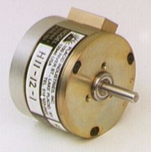
Exceptionally Stable & Reliable - Since torque is produced magnetically, across an air gap. Use the sizing information to select the proper brake.  | 
| Model H11-1 | 
Model(Click | 
     Torque Range (oz.-in.)  | 
     Input Electric Power (watts)  | 
     Shaft Inertia (lb.-in.-sec.2)  | 
     Slip Heat Dissipation (watts)  | 
     Overhung Load, Max. (lbs.)  | 
     Max. RPM  | 
     Weight (lbs.)  | 
     Data Sheets (Acrobat .pdf format)  | 
|
|---|---|---|---|---|---|---|---|---|---|
| Cover On | Cover Off | ||||||||
| H11 | 0.4 - 11 | 2 | 36 x 10-6 | 9 | 15 | 4 | 9000 | 0.7 | H11 data sheet | 
| H35 | 0.7 - 35 | 6 | 92 x 10-6 | 15 | 25 | 5 | 8000 | 2 | H35 data sheet | 
| H85 | 3 - 85 | 5 | 560 x 10-6 | 35 | 60 | 40 | 6000 | 4.5 | H85 data sheet | 
| H140 | 5 - 140 | 7 | 970 x 10-6 | 45 | 75 | 40 | 5000 | 6 | H140 data sheet | 
| H250 | 9 - 250 | 7 | 290 x 10-5 | 65 | 110 | 50 | 5000 | 9 | H250 data sheet | 
Available in 6, 12, 24, & 90 volts D.C.
The Brake Coil Specifications Chart shows rated current & coil resistance.
Dimensions are in inches.Model(Click | 
     Shaft | 
     Case | 
     Shaft-Shaft | 
     Case | 
     Shaft Length | 
     De-Cog Block | 
     Strain Relief | 
     Model(Click | |||||
|---|---|---|---|---|---|---|---|---|---|---|---|---|---|
B | 
     D | 
     E | 
     F | 
     G | 
     H | 
     L | 
     M | 
     N | 
     O | 
     P | 
     R | 
||
| H11 | 0.1872 | 1.80 | 2.75 | 1.25 | 0.75 | 1.09 | 0.43 | 0.28 | 0.75 | 0.2 (a) | 0.2 (a) | H11 | |
| H35 | 0.2496 | 2.31 | 3.50 | 1.75 | 0.87 | 1.49 | 0.57 | 0.28 | 1.235 | 0.35 | 0.4 | H35 | |
| H85 | 0.3746 | 3.32 | 4.80 | 2.30 | 1.25 | 1.9 | 0.70 | 0.53 | 1.40 | 0.55 | 0.50 | H85 | |
| H140 | 3.68 | 2.09 | 0.48 | H140 | |||||||||
| H250 | 0.4996 | 4.50 | 5.55 | 2.80 | 1.375 | 2.50 | 0.81 | H250 | |||||
 | 
     No. of | 
     Thread | 
     Basic Circle | 
     Mounting Pilot Diameter | 
     Mounting Pilot Length | 
|||
|---|---|---|---|---|---|---|---|---|
'C1' Side | 
     'C2' Side | 
     C1 | 
     C2 | 
     J1 | 
     J2 | 
|||
| H11 | 3 | #4-40 | 0.6875 | 1.625 | 0.500 | 1.000 | 0.08 | 0.05 | 
| H35 | #6-32 | 0.906 | 2.000 | 0.625 | 1.500 | 0.08 | ||
| H85 | #8-32 | 1.500 | 2.875 | 0.875 | 2.250 | 0.10 | ||
| H140 | 3.250 | |||||||
| H250 | #10-32 | 1.750 | 4.000 | 1.125 | 3.000 | 0.125 | ||